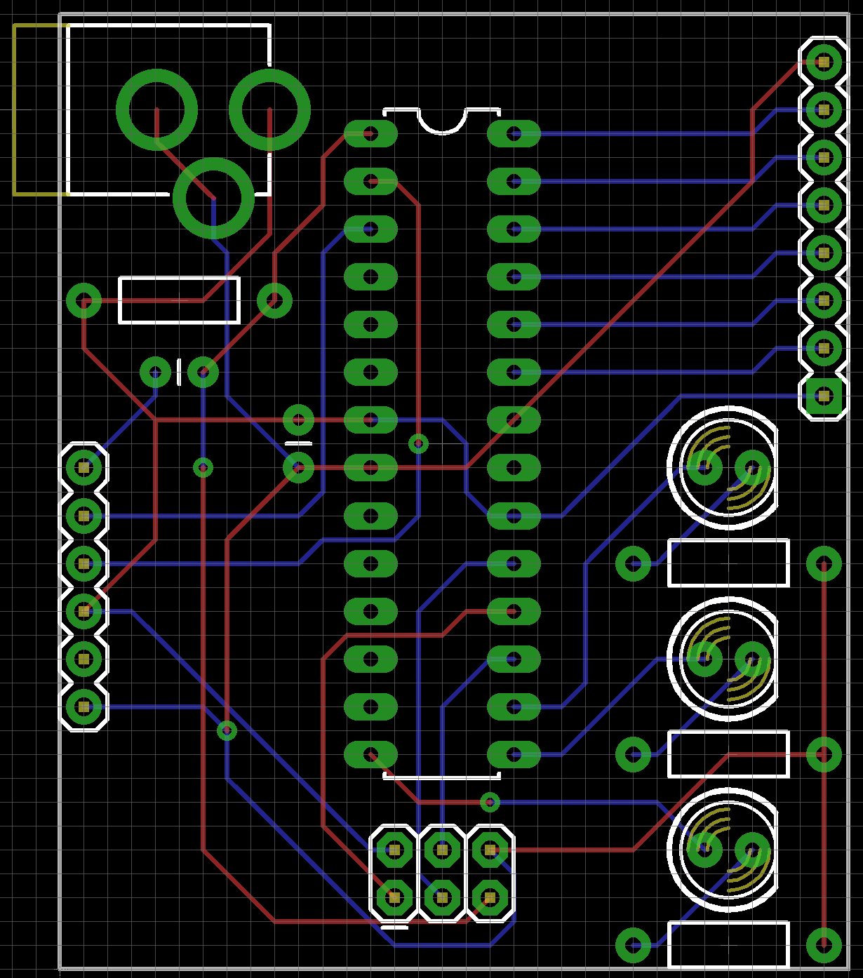
- Select the grey rectangle (the PCB Board) and in the Inspector change the layers-dropdown to 'one layer (single sided)'. Now hit the Autoroute-button in the bottom of.
- This tutorial about eagle cad. With describing the basic tools for the making single layer PCB at home by toner transfer method. FOR MORE: http://etech99.wix.
- Design a Single-layer PCB Using Eagle ECE480 Senior Design Team 5 Cheng Zhang Abstraction: This application note is a tutorial of designing a single-layer PCB using Eagle program. The tutorial will guild the reader through building schematic, designing PCB layout and generating CAM files in the Eagle program.
And it can generate Gerber files directly to JLCPCB which provide $2 for 5 pcs 2 layer PCB within 100mm x 100mm & $5 for 4 layer PCB. Mirko Bruno Sortini's ZentiPCB platform, which offers a range of free software to help users design their own PCBs. Historically, when most boards were single-layer, PCB ground pours were efficient as they provided a single point of reference. However, today multilayer PCB designs are more common. The reasons for this are many; including the ability to accommodate circuitry with higher complexity, flexibility to be installed in smaller, more compact products.
One of the most profound inventions that is not heralded as such is the safety brake for elevators. This device has enabled rapid movement across structures with over 150 floors or levels. Although the need for a safe and reliable way to vertically traverse multiple levels of structures existed for millennia, no one had devised a device to accomplish this until the mid-1800s. Finally, the problem was solved by Elisha Graves Otis, in 1852. To this day, the ability to safely move people between the multiple levels of vertical structures remains essential for civilization's continued development.
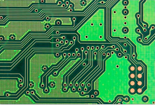
For electronic or printed circuit boards (PCBs), the ability to route electrical signals vertically has been an essential factor in the growth and deployment of electronics for an ever-increasing number of applications. By using surface mount devices (SMDs) and vias, multilayer boards can be made smaller than single layer boards and deployed into more compact products and locations. Today, the optimal number of layers primarily depends upon the application. First, let's take a look at the advantages of single; including single and double sided component mounting, and multiple layers then discuss how to design the best multilayer PCB.

Single Layer Versus Multilayer PCBs
There was a time when all boards were single layer, with components mounted on one or both sides, known as single-sided or double-sided, respectively. Although there are cases where single layer boards are preferable, there is an ever growing demand for smaller, more functional electronic devices. For these devices, multilayer PCBs are the better option as size can be reduced by increasing the number of layers. By building up instead of out, you gain the ability to route more complex traces, which allow for more capable circuits. To determine which is best for your design, it is helpful to compare the advantages of each, as shown below.
Single Layer PCB
- Advantages
- Only supports less complicated design
- Less complicated manufacturing
- Lower fabrication cost
- Easier to repair
- Applications
- Digital cameras and calculators
- Printers and photocopiers
- Relay and solid state drive circuits
- Coffee makers and digital microwaves
- LED lighting circuits
Multilayer PCB
- Advantages
- Can accommodate highly complex designs
- Can be deployed in compact locations
- High quality construction
- Very durable and reliable
- Applications
- Smart phones
- Smart TVs
- Healthcare devices
- Wearables
- Home monitoring equipment
The applications listed above are examples and both single layer and multilayer PCBs are used in many other applications. However, if size and/or complexity are primary factors, you will most likely benefit from a multilayer PCB design.
Multilayer PCB Design Tips
The focal point of multilayer PCB design is the stackup. There are a number of choices or selections that must be made for your layer stackup and these should be guided by functionality, manufacturing and deployment considerations.
Tip #1: Optimize your board size
Microsoft publisher 2007 free download crack. Download Microsoft Publisher 2007 for Windows to create, design, and publish professional marketing and communication materials. Download microsoft publisher 2007 exe for free. Office Tools downloads - Microsoft Office Publisher by Microsoft and many more programs are available for instant and free download. Jun 20, 2019 Microsoft Office 2007 Activator with Crack + Keygen + Patch also applies to Microsoft Office Project, Microsoft Office SharePoint Designe Windows Activator Loader Fully working Free Download Windows Loader, Activators, Product Keys, Serial Keys, Cracks, KMS Pico, Remove WAT, DAZ, Hazar, and more for Windows XP, Vista, 7, 8, 8.1, 10. For Dummies Microsoft Office Publisher 2007 For Dummies Dec 2007: Microsoft Office Publisher 2003 (serial) Microsoft Office Publisher 2007: Microsoft Publisher 2.0. Keygen is short for Key Generator. A keygen is made available through crack groups for free download. Site Information. Download Firefox Search Plugin Crack Serial Keygen Help Guide.
Setting your board size first will provide a constraint for determining other attributes of your multilayer PCB. Factors that determine the optimal board size are the number and size of components, location where the board will be mounted, and your contract manufacturer's (CM's) tolerances for spacing, clearances, and drill holes.
Tip #2: Optimize your layer design
Your layers should be designed and based primarily on signal types. To determine how many layers you need, you can use the following equation:
For layer optimization, you should also consider your impedance requirements, especially if fixed or controlled impedance is used.
Tip #3: Optimize your via selection
Your choice of via(s), blind, buried, through-hole or via-in-pad, is also important as it will affect the complexity of manufacturing and consequently the quality of your PCBs.
Tip #4: Optimize your material selection
Selecting the best material for your board's construction should be done on a layer by layer basis. However, signal layers and ground plane distribution within the stack should be symmetric and support good signal integrity.
Tip #5: Optimize the manufacture of your boards
The manufacture of your PCBs is performed by your CM. However, your design decisions and actions, beginning with the choice of CM and including clearances, drill hole sizes, solder masking options, trace parameters and other DFM guidelines, significantly impact the process.
Tempo‘s Custom PCB Manufacturing Service
|
Tempo Automation specializes in PCB turnkey manufacturing for prototyping and low-volume production. We are the industry leader in fast, high-quality custom board fabrication and assembly. As we work with you throughout the process and apply our software-driven advanced factory to meet your design objectives, you will have the best development experience possible.
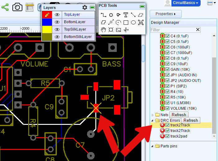
And to help you get started on the best path, we furnish information for your DFM checks and enable you to easily view and download DRC files. If you're an Altium user, you can simply add these files to your PCB design software.
Pcb Board Design Software
If you are ready to have your design manufactured, try our quote tool to upload your CAD and BOM files. If you want more information on multilayer PCBs or tips to optimize your design, contact us.
